

![]()
Titan Centering Microscope - Z-100
Click here for X Series Centering Microscope detail Specifications
Click here for Z & Y Series Centering Microscope detail Specifications
Z-100 = ZCS-006
Features:
The Titan Centering Microscopes are designed for job set-up and inspection with vertical milling machines, large jig borers, boring mills, lathes, electrical discharge machines, tape-controlled machines, drill presses. Three Coordinate Measuring Machines.
Titan Centering Microscopes have an upright image, optically correct from left to right so that the operator sees the workpiece with the microscope the same as without it, Mistakes due to transposing or converting are eliminated.
The X & Y & Z Series Centering Microscopes all come with hardened and ground 1/2” diameter shanks so that they are adaptable to all machines through the use of collets. It is suggested if it will be used continuously in one machine that it be fitted with its own collets.
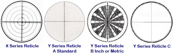
The most minute spindle run-out can be compensated for both the X & Y & Z Series Centering Microscopes the X Series uses the popular (3) master centering screw method where the reticle floats between the centering screws just below eyepiece of the microscope.
The Y & Z Series Centering Microscope have a “Prismatic” centering device where only two screws are needed for especially simple and fast centering to compensate for spindle run-out. The prismatic setting on the Y & Z Series has the advantage of not changing the settings of one axis while you are adjusting the other axis, as both settings are entirely independent of each other. Both methods can be quickly mastered. Special instructions come with the units. It is an easy matter to adjust the microscope for perfect centering every time.
- Surface finish can easily be checked with Model X-II and Y-II under 50X magnification.
- The drilling of printed circuit boards through prior location and centering.
- Details too small, or inaccessible to an indicator or edge finder can be easily picked up.
- A vertical mill or jig borer with optical scale or precise lead screws can be turned into a three coordinate measuring machine for checking the accuracy of completed dies, molds, castings and precision parts. These parts are sometimes too big to fit into a comparator or a Tool Maker’s Microscope table as these means of measuring the larger parts are too limited to check the job properly.
- The uses of 3 coordinate measuring machines can be greatly enlarged by their usage, Model Y-II specifically designed for this purpose.
- The human element of “feel or touch” is eliminated so all errors resulting from misreading micrometers, verniers and indicators is eliminated by the lack of physical contact between the operator and what he is measuring through the use of microscopes.
- Model Y-I is especially useful for setting up on Electrical Discharge Machines, because of its extra-long focal length and long eye-tube, made so the operator has easy access to the instrument over the closed tub or basin of the machine. (With some care the operator can learn to view the work-piece through clean oil, once the angle of distortion is calculated.) This eliminates constant draining between changing electrodes.
- The zero (0) or starting position for use on tape-controlled machinery can easily and quickly be plotted through their usage by sighting through the various positions needed in the work cycle and punching the tape accordingly.
- Model Z-I with low magnification and extremely long focal length is ideally suited for alignment on Boring Mills.
- Model Y-III with High Magnification depth Measurement of Minute Slots and Grooves by the difference in Focus Principal. Sight on the Bottom of the Groove zero an indicator attached to the Vertical Spindle, come to the top of the Groove and read the displacement on the indicator.
- Checking Printed Circuit Boards on Three Coordinate Measuring Machines for Size of Holes and Circuit Patterns.
X Series Centering Microscope - Correction for Spindle Run-out by the triangulation method (3 screws moving the reticle opposite to the spindle run out) Directions with unit.
- SHANK: 3” long, 1/2” diameter, hardened and ground.
- EYETUBE: 3 1/2” long at 45° angle to the center of the body.
- IMAGE: Optically correct. Right side up not inverted.
- EYEPIECE: Color coated and achromatic Kelner type.
CMI/CMT Illuminator & Transformer uses 6 EL-17 Bulbs, 110 Volt Power Supply with North American Plug Type


